WHY PEMALL 5112TM ENGINEERED SYSTEM?

PEMALL 5112TM Engineered System is supplied in stainless steel cylinders of wide filling ranges that offers small footprint that requires minimal storage space.  It has a boiling point of 49°C and therefore exists as a liquid at room temperature.  Super-pressurized with nitrogen to 500 psi it rapidly extinguishes a fire through a combination of heat absorption and some chemical interference with the flame.

The PEMALL 5112TM cylinders are supported with the option to be designed with the Selector valve options where cylinders are connected to a manifold pipe which runs into the selector valve manifold. Each protected area zone is connected to a separate selector valve that pneumatically or electrically operated so when fire is detected the control panel opens only the related zone selector valve to discharge agent into the affected area. If the fire is detected in a different zone, the control panel opens the selector valve related to that respective zone.

The PEMALL 5112TM 500 psi with PEMALL FK-5-1-12 system is extremely flexible where the innovative cylinder filling range, Head Valve connection options of Electrical, Pneumatic, & Manual connections as well as the Selector “Directional“ Valve option support to have designs  that  save space and reduces both installation and maintenance costs.

PEMALL 5112TM safeguard a wide range of applications: Offshore Facilities, Petrochemical Plants, Marine Chemical Plants, Military Vessels, Industrial Military Sites, Power Plants, Industrial Complexes and Renewable Energy Sites.


ADVANTAGES

PEMALL 5112TM  Fire Suppression System – Extinguishment capability occurs within seconds, via a combination of chemically based fire inhibition and cooling at the flame front. Extinguishing concentration is reached in seconds.

Ozone Depletion Potential (ODP) – PEMALL FK-5-1-12 fluid is a highly fluorinated ketone containing no chlorine or bromine meaning it has no effect on stratospheric ozone with ZERO ODP.

Global Warming Potential (GWP) – PEMALL FK-5-1-12 fluid has an atmospheric lifetime of only 0.014 years. The global warning potential for all practical purposes is almost negligible.

PEMALL 5112TM Fire Suppression System  are necessary to:

 Minimized space and weight requirements
 Faster installation and service 
 Ambient temperature storage.

NOTE : 

• All cylinders are manufactured with high grade quality of Stainless Steel Grade 304 while 316L is also available upon request.
• Cylinders are available in Mirror Surface finished or painted in Flame Red color  when it supplied to clients.
• The Model Numbers indicated on this page has an equivalent UL Part Number. Please contact the manufacturer for any verification purposes.


PEMALL STAINLESS STEEL CYLINDERS

PEMALL USA uses specially designed Stainless Steel storage cylinders of wide filling range that are pressurized to 500 psi that enable you designing your system to use the smallest cylinder , storage space for the required quantity of agent that saves money and floor space.


500 PSI (34.5 BAR) SYSTEM

The PEMALL-5112TM High Pressure (HP) Series consists of a clean agent fire extinguishing system that utilizes UL Listed and FM approved FK-5-1-12mmy2 fire protection fluid which is commercially known as PEMALL FK-5-1-12. HP Series permits higher discharge rates and is particularly adaptable to areas requiring larger quantities of agent or discharge duration is challenge.


Assembly Model Number Cylinder Size Max Fill at 70 lb/ft3 Min Fill at 30 lb/ft3 Valve Size
F5-SS*-0025-1.0 25 LB 21 LB 11 LB 1" Valve
F5-SS*-0040-1.0 40 LB 38 LB 18 LB 1" Valve
F5-SS*-0075-1.0 75 LB 76 LB 36 LB 1" Valve
F5-SS*-0105-1.0 105 LB 108 LB 51 LB 1" Valve
F5-SS*-0105-1.5 105 LB 108 LB 51 LB 1 1/2" Valve
F5-SS*-0155-1.5 155 LB 163 LB 77 LB 1 1/2" Valve
F5-SS*-0255-1.5 255 LB 271 LB 127 LB 1 1/2" Valve
F5-SS*-0380-2.5 380 LB 406 LB 190 LB 2 1/2" Valve
F5-SS*-0565-2.5 565 LB 601 LB 281 LB 2 1/2" Valve
F5-SS*-0665-2.5 665 LB 712 LB 333 LB 2 1/2" Valve
F5-SS*-0665-3.0 665 LB 712 LB 333 LB 3" Valve
F5-SS-0850-3.0 850 LB 900 LB 420 LB 3" Valve
F5-SS-1100-3.0 1100 LB 1112 LB 520 LB 3" Valve
F5-SS-850-4.0 850 LB 900 LB 420 LB 4" Valve
F5-SS-1100-4.0 1100 LB 1112 LB 520 LB 4" Valve
F5-SS-1250-4.0 1250 LB 1297 LB 606 LB 4" Valve


PEMALL-5112TM HP Series standard arrangement consists of the following components and their associated accessories:

1. CYLINDER ASSEMBLY
2. ACTUATION UNITS
3. SUPERVISORY SWITCHES
4. MANIFOLD ACCESSIORES
5. DISTRIBUTION NOZZLES
6. INITIATION SWITCHES
7. INSTRUCTIONAL SIGNS
8. DETECTION AND CONTROL

CATALOGUES PEMALL 5112TM ENGINEERED SYSTEM - HIGH PRESSURE (HP) SERIES
COMPANY PROFILE PEMALL USA COMPANY PROFILE
BROCHURE PEMALL USA PEMALL 5112 - STAINLESS STEEL BROCHURE
BROCHURE PEMALL 5112 PRODUCT LINE
BROCHURE PEMALL CLEAN AGENTS - HFC-227EA AND FK-5-1-12

SYSTEM ACCESSORIES

PEMALL CYLINDERS

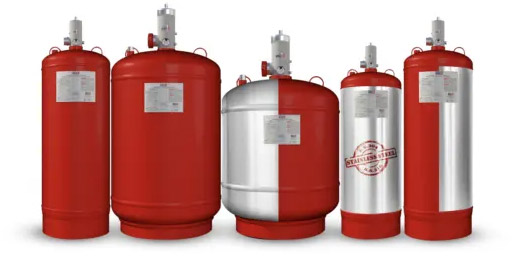
PEMALL cylinders is comprised of fully integrated stainless steel cylinders and accessories. We offer different sizes of Stainless Steel Cylinder ranging from 25 lb, 40 lb, 75 lb, 105 lb, 155 lb, 255 lb, 380 lb, 565 lb, 665 lb, 850 lb, 1100 lb and 1250 lb. Our cylinders are UL Component recognized, providing our customers assurance of high quality products to maximize the potential of the Clean Agent.


HEAD VALVES

PEMALL Head Valves are made by our engineers through a well controlled investment castings to ensure rigidity and durability. With our unique design, we have attained approvals from international standard bodies which are DOT, UL, TPED, GOST, and FM.

The head valves are back pressure type valves. A piston in the valve is equipped with a rubber seal that keeps the Clean Agent under pressure within the cylinder.

FEATURES

- Accurate Back Pressure Control
- Thorough Laboratory Testing
- Threaded Connections
- High Speed  Response
- Debris Protection
- Long Service Life


CYLINDER BRACKET

Securely mounts the cylinder to support its load. The cylinder bracket should be mounted  on a solid load bearing concrete wall. The cylinder stainless steel bracket is chosen as primary means of support, as they enable the gas cylinders to be held tightly and securely during an event of Clean Agent discharge. It is also installed to protect the cylinder from any obstructive positioning.


LIQUID LEVEL INDICATOR

Liquid level indicator determines the amount of liquid level in the clean agent cylinder. Once the liquid level is determined, it can then be converted into pounds (kilograms) of Clean Agent present in the agent storage container.

Model Number Description

LLI-0255

LIQUID LEVEL INDICATOR 155/255 LB CYLINDER

LLI-0565 LIQUID LEVEL INDICATOR 380/565 LB CYLINDER
LLI-0665 LIQUID LEVEL INDICATOR 655 LB CYLINDER
LLI-0850 LIQUID LEVEL INDICATOR 850 LB CYLINDER
LLI-1100 LIQUID LEVEL INDICATOR 1100 LB CYLINDER
LLI-1250 LIQUID LEVEL INDICATOR 1250 LB CYLINDER

NOTE:
The Electrical solenoid can be removed for servicing or testing without loss of agent since the SCHRADER (check valve) will close as The Electrical solenoid is removed.

ELECTRICAL ACTUATION UNIT - LATCHING SOLENOID

Our latching solenoid is designed to meet requirements of NFPA 2001, UL 2166, UL 2127 and FM 5600. It is assembled on top of the top plug adapter of the head valve in order to release the extinguishing medium with an electrical current or manual activation via the local manual control. Activation through a push rod that depresses a Schrader valve thereby venting the pressure from the top of the piston in the cylinder valve, allowing the piston to slide upward to commence the clean agent discharge.

Specifications
Weight 2.66 lbs (1.3 kg)
Body Diameter 1.77 in (45 mm)
Length 5.10 in (129.5 mm)

MANUAL ACTUATION UNIT

A manual lever and cam arrangement on the actuator permit actuation of the device on a manual basis, thereby overriding and independent of electric power or pneumatic pressure. A pull pin and seal prevent accidental operation of the manual lever. A swivel nut and O-ring seal on the device provides for attachment and seal at the connection point under part number LMCLA-01.

  • Used for manual actuation  of cylinder
  • Equipped with safety pull-pin  to prevent accidental manual discharge of Clean Agent
  • Self-venting
  • Solid brass construction
  • Stainless steel operation lock-pin

NOTE:
Flexible connectors are used to interconnect the cylinder valve devices. These hoses have a stainless-steel wire braid cover and a Teflon liner, and are fitted at each end with a 1/4 in. swivel flare nut.

PISTON ACTUATOR CONTROL HEAD-SLAVE

The Piston Actuator mounts directly to a Top Plug Adapter of the cylinder valve. It features a pneumatically driven piston that depresses a Schrader Valve, thereby venting the pressure from the top of the piston in the cylinder valve, allowing the piston to open and commence cylinder discharge.

Actuation of the master or prior slave cylinder valve assembly permits pressure to be applied through a flexible connector set connected to the pneumatic actuator, which in turn applies pressure to its operating piston.

LOW PRESSURE SUPERVISORY SWITCH

The low pressure supervisory switch can detect a drop in pressure. One version of the switch is normally closed (N.C) and the second version is normally open (N.O.). The switch is referenced in the no pressure condition. When the cylinder is pressurized until the actuation pressure is reached, the contact for the normally closed (N.C.) switch will shift from normally closed to normally  open status and vice versa for the normally open (N.O.) switch.

Electrical Rating
120 VAC 5.8FLA, 4.8LRA
240 VAC 2.9FLA, 15LRA Snap
24 VDC 125VA Pilot Duty
28 VDC 2 Amps

PRESSURE OPERATED SWITCH (N.C./N.O.) SPDT (MANUAL RESET)

This switch is used for sending a signal to the control panel when the clean agent is manually released. It is provided to furnish additional electrical contacts for control purposes at the time of discharge. An external manual reset button is provided on the pressure switch.

Specifications
Electrical Rating 15 Amps - 125/250 VAC
Switch SPDT Snap Action
Contacts One. N.O and One N.C
Activating Pressure 10 - 100 psi

PRESSURE OPERATED SWITCH (N.C./N.O.) SPDT (AUTOMATIC RESET)

The switch is used for sending a signal to the control panel when a system discharge happens. It provides electrical contacts for alarm and auxiliary functions.

Specifications
Electrical Rating 5 Amps. Resistive 110 V/ 250 VAC, 3 Amps.
Inductive 28 VDC. SPDT Snap Action
Temperature -65°F 280°F
Pressure Connection 1/8" NPT-Male
Electrical Connection 8" Pigtails

DISCHARGE HOSES

Flexible hoses are used to connect the stainless steel cylinders to the manifold in multiple cylinders arrangement. Flexible hoses are 18″ long and constructed of high pressure hydraulic rubber in the 1″ and 1-1/2″ sizes or stainless steel corrugated inner core with stainless steel braided in the 2-1/2″, 3″ and 4″ sizes. All sizes except for the 3″ and 4″ flex hose are fitted with male NPT threads on both ends. The 3″ and 4″ version has a grooved fitting on both ends.

Model Number Diameter Material
FH-0100 1” Rubber
FH-0150 1-1/2” Rubber
FH-0250 2-1/2” Stainless Steel Braided
FH-0300 3” Stainless Steel Braided
FH-0400 4” Stainless Steel Braided

CHECK VALVES

The Check Valves are used to prevent the loss of clean agent in the event that any of the stainless steel cylinders are not connected to the manifold at the time of system discharge. Also, to prevent back flow of the clean agent into the other stainless steel cylinders attached to the manifold.

Model Number Description Valve Size
CV-0100 Check Valve Assembly 1”
CV-0150 Check Valve Assembly 1-1/2”
CV-0250 Check Valve Assembly 2-1/2”
CV-0300 Check Valve Assembly 3”
CV-0400 Check Valve Assembly 4”

DISCHARGE NOZZLE

PEMALL USA fire extinguishing systems are designed to be discharged within 10 seconds into designated area, room, or enclosure with the structural integrity to retain the agent as well as achieving a minimum concentration level in accordance with NFPA 2001 and/or agency listings in that regard. PEMALL USA system nozzles are designed & constructed from Aluminum as well as Stainless steel with  360° and 180° nozzle  configuration to ensure proper discharge and  distribution of agent as per the design parameters.

Model Number Valve Size
NZ-SS-0050S-.XXXX ½” (180°) Sidewall
NZ-SS-0050C-.XXXX ½” (360°) Central
NZ-SS-0075S-.XXXX ¾” (180°) Sidewall
NZ-SS-0075C-.XXXX ¾” (360°) Central
NZ-SS-0100S-.XXXX 1” (180°) Sidewall
NZ-SS-0100C-.XXXX 1” (360°) Central
NZ-SS-0125S-.XXXX 1 ¼” (180°) Sidewall
NZ-SS-0125C-.XXXX 1 ¼” (360°) Central
NZ-SS-0150S-.XXXX 1 ½” (180°) Sidewall
NZ-SS-0150C-.XXXX 1 ½” (360°) Central
NZ-SS-0200S-.XXXX 2” (180°) Sidewall
NZ-SS-0200C-.XXXX 2” (360°) Central


YELLOW CAUTION SIGN

The Yellow Caution Sign has dimension of 14″ x 10″ x 1/16″ (356 x 254 x 1.5 mm) and is constructed of plastic with a yellow background.

MANUAL DISCHARGE STATION SIGN

The sign has a dimension of 4″ x 4″ x 1/16″ (100 x 100 x 1.5mm) and is made of plastic with white lettering on a red background.


FLASHING LIGHT SIGN

The sign has a dimension of 7″ x 4 1/4″ x 1/16″ (178 x 108 x 1.5 mm) and is made of plastic with white lettering on a red background.

CAUTION (WHEN ALARM SOUND ... )

The purpose of this sign is to alert personnel to evacuate the protected area. The sign should be conspicuously located near alarm devices.

CAUTION (DO NOT ENTER ROOM ... )

The purpose of this sign is to prevent personnel from entering a protected area. The sign should be conspicuously located outside the entrance door to the  protected area.

CAUTION (OPERATION OF MANUAL STATION WILL ... )

The purpose of this caution sign is to instruct personnel as to use of the Agent Release Manual Pull Station. The sign should be installed adjacent to all Agent Release Manual Pull Stations.

RELEASING CIRCUIT DISABLE SWITCH

The Releasing Circuit Disable Switch is UL Listed and has a dual functions. One is to cut the circuit continuity of the electric solenoid, and another is to give a signal to the control panel to indicate that there is no circuit continuity in the electric solenoid to initiate the discharge of the agent.

ABORT STATION

The Abort Station causes the agent release circuit to be manually delayed. Upon release of the Abort Station, the release circuit will follow the specific configuration of the UL Listed Control Panel. It provides a temporary manual mean, whereby the system actuation circuit may be interrupted when operated prior to the circuit actuation.

MAIN RESERVE SWITCH

The “Main” to “Reserve” Switch is used with systems that incorporate main and reserve (back-up) agent storage. The switch may utilize 1 or 2 Form “C” Contact Blocks, which will provide an electrical path to either the “Main” or “Reserve” cylinder electric solenoid.

PNEUMATIC ACTUATOR ASSEMBLY

Pneumatic Actuator provides effective solutions for the most complicated flow requirements , including diverting and multi-port flow applications for the fire suppression system. Our pneumatic actuator assembly is complete with all of the control accessories required particularly the Limit Switch Box and Selector Valve.

Model Number Sizes of Selector Valves
SV-0200-16 2"
SV-0250-16 2-1/2"
SV-0300-19 3"
SV-0400-19 4"
SV-0600-25 6"

Top